Version 3.0 Ready for FINAL test build
Well, it's been a semi-long road, but i'm finally ready to build the complete unit. i'll recap what i've done since my last post.
i solved the accelerometer non-linear output issue. my delay loop was the culprit. before explaining the solution, it's important to understand the problem.
how am i determining steps per minute? one method is to keep a counter that allows me to track how much time has passed directly. that is, every 10 microseconds i increment a counter, and simply count how much time has passed and deduce steps per minute. for example, if 1 second passes between each step, that means the user is taking a step 60 times per minute, or 60 steps per minute. likewise, if 0.5 seconds passes between each step, the user is taking 2 steps every second, or 120 steps per minute. easy right?
i'm not so crazy about using time dependency like that because it relies too heavily on the accuracy of my timer. this is bad because time is highly dependent on the speed of the processor.
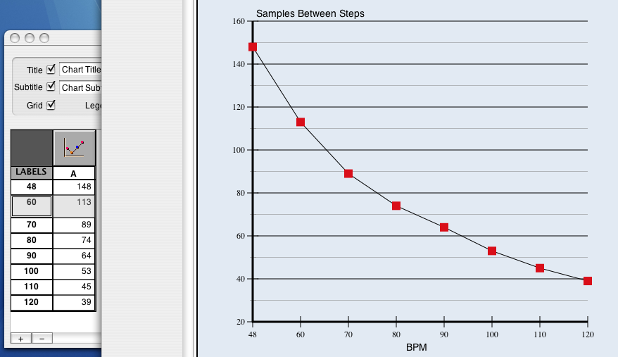
an alternative method to using time directly, is to measure time indirectly. we can do this by looking at how many samples the accelerometer has output. why? well, what is a sample rate? it is the number of samples that occur PER SECOND. that means the sample rate is a time-based measurement, but doesn't depend on the pic's clock speed. so how can we use the sample rate? well, first we need to know the sample rate of the accelerometer. for example's sake, let's say the accelerometer outputs 100 samples per second, a sample rate of 100hz. we can count how many samples are output by the accelerometer, by simply reading one complete pulse from the pulse wave. since we can do that, we can count how many samples are output between each step that is detected. continuing with our example, if the sample rate is 100 hz, and lets say we are busy reading samples, incrementing our counter every time one sample is read. if we read 100 samples, then detect a step, then read another 100 samples, then a step, how fast is the user walking? well, the user is taking 1 step every 100 samples, and we know that 100 samples are output every 1 second, thus the user is taking 1 step every second. likewise, if we read 50 samples then detect a step, then read another 50 samples, and detect another step, how fast is the user walking? the user is taking 1 step in every 50 samples, and we know that 50 samples is half 100, so half a second. thus, the user is walking 120 steps per minute.
now, the samples quite short. in fact, the accelerometer i have has a sample rate of 138hz; that's a full sample every 7 milliseconds. needless to say, when we are detecting how many samples go by, miniscule errors in the human step pattern result in large variations. no one can step to a beat with an accuracy of 7ms. so, if the system is off by the tiniest bit, the number of samples that we see occurring between each step detected will be greatly affected. while we might expect stepping at 60 steps per minute would be 138 samples, and 120 steps per minute would be half that (~70 samples), my incorrect code was only reading 40 samples at 120 steps per minute. that's less than half the number of samples that occur at 60 steps per minute, which doesn't make sense. it should be roughly half.
fine. so that was the issue. here's how i fixed it:
because the accelerometer is quite sensitive, and measuring vibration leads to an incredibly rough signal (the accelerometer's output looks like the output from a seismograph), we need to do some filtering so that we only count real steps. one step could be seen as 5-6 depending on how closely we look at the accelerometer's output. while i have tried several algorithms to filter the output, the most trivial method worked the best: if the accelerometer's output is large enough, we detect it as a step. this simple one beat out peak and valley measuring, dynamic max/min comparisons, windowed filtering, etc. while i'd like to say i created some nice algorithm to filter it, i can't; the stupid algorithm was the best.
so, the moment i detect a step, i punt out of reading the accelerometer, compute the steps per minute, AND (here's where the error occurred) i then did nothing for 250 milliseconds.
but why?
well, my reasoning was, the moment we see a step, we can simply ignore the next 250 milliseconds because a step every 250 milliseconds is approximately 300 steps per minute. that's very fast. i don't know many people that run that fast in normal situations. so, i figured hey just wait 250 ms then start reading again. that way, i don't count all the garbage vibrations that occur with every step. this was the error in my code.
first, the accelerometer does not output at a constant sample rate. instead, the sample rate is allowed to fluctuate, but the ratio between the on time of the pulse and the off time is always consistent. that means, the sample rate could drop to 80, but the pulses would be sized accordingly. armed with this new information, i set out to make my delay smarter. instead of just waiting a blind 250 ms, i decided to count a certain number of samples, in order to compensate for the changing sample rate. that way, i'd know that after each step, i ignored exactly 30 samples before resuming the program.
this also failed. why?
i wrote some code to output the length of each pulse as it was read. then i tested it. sure enough, the sample rate wasn't varying that much, and only varied when i took a step. we're talking 5-7 samples more or less when a step was taken. was it really THAT big a deal?
then i remembered the time scale i was measuring: one sample was only 7 ms. the slight variation in sample rate could throw the samples off by 5-7, and since that error was created each time i took a step, then the more steps i took per second, the more error accrued. ERRORS ARE CUMULATIVE! so, stepping at 60 steps per minute, i'm only incurring an error once per second, so the overall steps per minute calculation would be off by around 5 samples. not a big deal, but at 180 steps per minute, i was incurring somewhere around 15-21 sample errors. this was further exacerbated by the fact that higher steps per minute usually meant more vigorous vibrations which lead to larger sample rate variations.
so what i was assuming is that ignoring 30 samples would be the same amount of time delayed for each steps per minute. what's in fact happening is the length of time 30 samples takes is different for each steps per minute interaction. at 180 steps per minute, 30 samples a different amount of time than at 60 steps per minute.
my solution was to change the filtering from time-based to sample-based (in a different way). first, i removed the delay, tried it out, and saw that overall the samples were coming out correctly (138 for 60 steps per minute and 69 for 120 steps per minute). however, now i was detecting 2-3 steps for each real step that occurred. my new solution was this:
step detected?
if yes:
        was the step humanly possible?
        if yes:
                blink led
                calculate steps per minute
                send steps per minute out serial line
        if no:
                ignore
so what does humanly possible mean? well, i sat down and tapped this circuit at 300 beats per minute and how it tell me how many samples it was reading between each tap at that pace. it was able to read 30 samples between each step at 300 beats per minute. so humanly possible means, did you read at least 30 samples? now, the device will say "hey i saw a step" multiple times for a single step that actually occurrs, but it won't DO anything about it unless enough samples have been read since the last step. simple solution, perfect results.
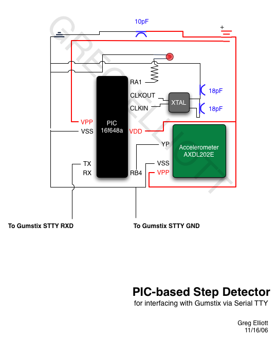
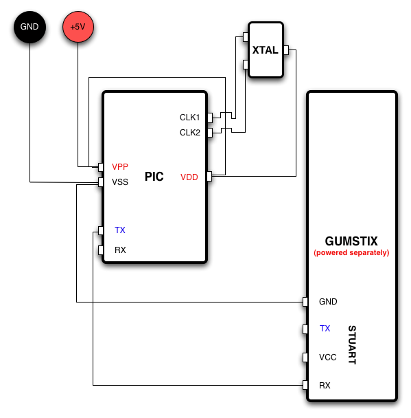
now everything is working. next step is to build the prototype board (no breadboard) in a very small size using a pic socket ( so i can reprogram it as needed after real-world testing), and solder everything up to the gumstix board. simon penny has given me a bunch of non-rechargeable li-ion batteries that i can use for testing. i'll be ordering some 1000mhA li-ion batteries from sparkfun that are rechargeable.
tom has ordered some pic sockets, and hopefully they'll be here soon.
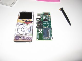
so in the end, it seems i've been able to take a large, belt-mounted power hungry device and shrink it down into a device that's the same size as my ipod nano, uses less power, and is SIGNIFICANTLY less computationally expensive.
:)
posted by kolywater @ 4:31 PM
0 comments
![]()